As previously mentioned, I am a ham nerd. Yep, I like listening to the radio. Morse code? Never touched it. That's alright though, modern technology has removed the requirement for knowing those sorts of things (almost). For instance, using computers to handle that work for us. Of course someone had to know it to make the software originally. But collaborative works are like that, you each do your part for the greater good.
Enter Fldigi. It's, simply put, a modem that runs off a sound card. It comes with a plethora of operating modes and data rates and allows for very available methods to do digital transmissions using your radio. I will have to point out that the first night I tried this I did not do any transmissions. I just listened in. Locally I found the VOR of our airport sending out it's identifier, tuned in, and watched Fldigi do it's magic.
Some configuration was required but it was trivial. Set the mode to CW, zero'd in on the frequency, and it automagically detected the rate. Then there it was... typing slowly out... my local airport's identifier. Very, very, very cool.
Here's what I needed:
My Yaesu FT-60R
Pryme Hand Mic
Male-Male 3.5mm 3 conductor (stereo) cable
My Computer, running Ubuntu whatever - it's up to date.
Steps to achieve to this:
Turn radio on tune to frequency performing digital transmission (or CW in my case)
Plug hand mic into radio
Plug audio cable into Headphone jack of hand mic
Plug audio cable into aux line in, or Microphone of computer
Install Fldigi: sudo apt-get install fldigi; fldigi &
Go through and configure your options, ignoring PTT for the moment
You should see the waterfall (pretty blue, yellow, orange) flowing at the bottom
Move the Red-box over the band of yellow/orange which looks like morse code
Magic happens.
Presto that's it!
Monday, February 28, 2011
Thursday, January 27, 2011
Modding My Yaesu FT-60R
Yes, I am a Ham Nerd...
The decision to become a ham was a actually made years ago. Though I didn't pursue it then... I've since come to realize that telecommunications are as very important to my life as verbal and non-verbal communication. I spend a lot of time on the Internet and the radio.
Alright, not as much on the radio as other hams. But I do enjoy catching the local nets from time to time. Hearing the other people out there, being able to chit-chat with the locals and the DXers (if I get the opportunity). Get to hear some fascinating things... especially about Medicare and rascal scooters.
So I get it into my head to modify my FT-60R, the reasons are because it should be fairly easy, will exercise some basic de-soldering skills, and these modifications would open up my radio's ability to transmit from 137-174 Mhz and 420-470 Mhz. I'll need to check this per country, but I believe this may come in handy elsewhere (literally). Not to mention, as my friend Bill Wells always said... "Carry an umbrella and it won't rain." In the highly unlikely event it was ever actually needed, it would be available.
In the U.S. as an amateur you may transmit between 144-148Mhz and 420-450 Mhz. Obviously this modification would open me up to the possibility of legal issues in the U.S. if I were not careful. Luckily I am familiar with these specifics so keeping within our little play pin in the U.S. should be no problem what so ever. In fact I keep a reference copy of the ARRL US Amateur Radio Bands on my cell phone for reference (ham nerd, remember?)
Now, the mod... I read someone else's work on this. Originally I read this when I first bought my radio and wasn't sure if I'd actually give it a try. But after watching a bunch of videos on SMT, I thought this may be an excellent way to ease into that sort of thing. The article I followed may be found here.
So this is not a terribly complicated process, in fact it's pretty simple. Just remove 1 resistor. Remove 1 very, very, very small resistor. Remember when I said it'd be fairly easy, exercising basic de-soldering skills? Well it would have been. If it wasn't for this...

Turns out buying a radio from the reds in China is both cheaper and will come without a band filter. So it would appear my radio already has the ability to transmit at it's highest potential, since it's missing that little resistor and all. A job well... um... easily... um... not done by me at all. But the radio went back together pretty smoothly ^_^ once I remembered to the put the battery clip back on before putting the screws in again.
Cheers
Wednesday, January 12, 2011
ASCII Experimenter's Coding and Process, Part 1
First blog of the new year, I am excited.
All inventions start with an idea. That idea is grown over time into a design. The design is formalized and then you can start building, prototyping, discovering those things you may have missed and need to be fixed. That's where I am right now, redesigning portions of my little device. Originally I was thinking I could drive whole rows with the 74HC08's. These devices have a maximum current rating of about 25mA, which frankly isn't enough to run 4 x 20mA LEDs simultaneously. I say 4 because the 8 are split across 2 chips. Luckily I can still use them, I just need to be a bit creative.
By arranging my 2 shift registers (74HC164) in a rectangular fashion I can form a grid space of 64 states. Conveniently I have 64 LEDs I may be interested in driving, what providence! Now my 74HC08's can only drive 1 LED at a time each because the Red LEDs in my matrix run at 20 mA and I'd like to maximize this current flow for the effect of viewing the LEDs.
So if I shift in a 1 into both the row and column registers and set the OUT_EN, output enable (which ties into the 74HC08s), HIGH and then the first LED in the corner will turn on. The row register activates the current sinking transistor which will sink the current sourced from the selected 74HC08 pin.
So let's look at how to do this in code. Unfortunately I've skipped the process of designing and watching this code fail (a lot), so I will only be sharing the more decidedly interesting parts of the program in the articles to come. Most of which revolves around getting the data into the chip to begin with. Keeping in mind this is my first ever electronics project of my own design.
Right... code... I assume all I/O has been correctly setup (and I'll show this in the future) for now I'll make a little function called displayMatrix(), void return type and no arguments. Parameters are passed in global memory space (aka the stack). This function also relies on a delay function, which is a small tight loop to add a short delay of a couple of cycles, I'll include this as well:
{
volatile unsigned int k;
k = DELAY_TICKS;
while(k>0)
k--;
}
This does have some requirements, for instance due to the nature of the >> and & logic I use, it requires the OUT_EN (P1.0) to be the LSB. All other pins I believe are safe from this restriction and may be moved about at will, as long as you remember to setup the bits in the #define section correctly. Of interesting note, using the TI MSP430- Launchpad I originally used P1.3 for the COL_CLK, this led to a drastically unreliable display.
As it turns out, there is enough noise on this pin when using the launchpad to trigger the 74HC164 clock an extra time or more when transitioning! This noise is caused by a switch attached to that same pin [image to come]. Rather than adding hardware to fix this, I merely avoided it's use, though I do plan on using it with 74HC151 in the future on that pin, but it'll be as an input instead of an output.
This code turns on 1 pixel at a time and splits the entire on time across all 64 pixels, displaying or not. This gives it a uniform brightness which I believe is desirable. My question to everyone else out there.
All inventions start with an idea. That idea is grown over time into a design. The design is formalized and then you can start building, prototyping, discovering those things you may have missed and need to be fixed. That's where I am right now, redesigning portions of my little device. Originally I was thinking I could drive whole rows with the 74HC08's. These devices have a maximum current rating of about 25mA, which frankly isn't enough to run 4 x 20mA LEDs simultaneously. I say 4 because the 8 are split across 2 chips. Luckily I can still use them, I just need to be a bit creative.
By arranging my 2 shift registers (74HC164) in a rectangular fashion I can form a grid space of 64 states. Conveniently I have 64 LEDs I may be interested in driving, what providence! Now my 74HC08's can only drive 1 LED at a time each because the Red LEDs in my matrix run at 20 mA and I'd like to maximize this current flow for the effect of viewing the LEDs.
So if I shift in a 1 into both the row and column registers and set the OUT_EN, output enable (which ties into the 74HC08s), HIGH and then the first LED in the corner will turn on. The row register activates the current sinking transistor which will sink the current sourced from the selected 74HC08 pin.
So let's look at how to do this in code. Unfortunately I've skipped the process of designing and watching this code fail (a lot), so I will only be sharing the more decidedly interesting parts of the program in the articles to come. Most of which revolves around getting the data into the chip to begin with. Keeping in mind this is my first ever electronics project of my own design.
Right... code... I assume all I/O has been correctly setup (and I'll show this in the future) for now I'll make a little function called displayMatrix(), void return type and no arguments. Parameters are passed in global memory space (aka the stack). This function also relies on a delay function, which is a small tight loop to add a short delay of a couple of cycles, I'll include this as well:
#define LEDS P1OUT
#define OUT_EN 1
#define ROW_DATA 2
#define ROW_CLK 4
#define COL_DATA 16
#define COL_CLK 32
#define DELAY_TICKS 30
#define OUT_EN 1
#define ROW_DATA 2
#define ROW_CLK 4
#define COL_DATA 16
#define COL_CLK 32
#define DELAY_TICKS 30
void displayMatrix(void)
{
volatile unsigned int row;
volatile unsigned int col;
LEDS &= ~(OUT_EN | ROW_DATA | COL_DATA | ROW_CLK | COL_CLK); //Clear data and output enable
LEDS |= ROW_DATA; //Set row data lines, start at row 1.
LEDS ^= ROW_CLK; //Clock row data in
LEDS ^= ROW_CLK;
LEDS &= ~(ROW_DATA); //Disable row data
for(row = 0; row < 8; row++) //Rows
{
LEDS |= COL_DATA; //Set column data, start at column1.
LEDS ^= COL_CLK; //Clock column data in
LEDS ^= COL_CLK;
LEDS &= ~(COL_DATA); //Disable column data
for(col = 8; col > 0; col--)//Columns
{
LEDS |= OUT_EN & (matrix[row] >> (col-1) & 0x01); //Enable output
delay();
LEDS &= ~(OUT_EN); //Disable output.
LEDS ^= COL_CLK; //Next column
LEDS ^= COL_CLK;
}
LEDS ^= ROW_CLK; //Next row
LEDS ^= ROW_CLK;
}
}
void delay(void){
volatile unsigned int row;
volatile unsigned int col;
LEDS &= ~(OUT_EN | ROW_DATA | COL_DATA | ROW_CLK | COL_CLK); //Clear data and output enable
LEDS |= ROW_DATA; //Set row data lines, start at row 1.
LEDS ^= ROW_CLK; //Clock row data in
LEDS ^= ROW_CLK;
LEDS &= ~(ROW_DATA); //Disable row data
for(row = 0; row < 8; row++) //Rows
{
LEDS |= COL_DATA; //Set column data, start at column1.
LEDS ^= COL_CLK; //Clock column data in
LEDS ^= COL_CLK;
LEDS &= ~(COL_DATA); //Disable column data
for(col = 8; col > 0; col--)//Columns
{
LEDS |= OUT_EN & (matrix[row] >> (col-1) & 0x01); //Enable output
delay();
LEDS &= ~(OUT_EN); //Disable output.
LEDS ^= COL_CLK; //Next column
LEDS ^= COL_CLK;
}
LEDS ^= ROW_CLK; //Next row
LEDS ^= ROW_CLK;
}
}
{
volatile unsigned int k;
k = DELAY_TICKS;
while(k>0)
k--;
}
This does have some requirements, for instance due to the nature of the >> and & logic I use, it requires the OUT_EN (P1.0) to be the LSB. All other pins I believe are safe from this restriction and may be moved about at will, as long as you remember to setup the bits in the #define section correctly. Of interesting note, using the TI MSP430- Launchpad I originally used P1.3 for the COL_CLK, this led to a drastically unreliable display.
As it turns out, there is enough noise on this pin when using the launchpad to trigger the 74HC164 clock an extra time or more when transitioning! This noise is caused by a switch attached to that same pin [image to come]. Rather than adding hardware to fix this, I merely avoided it's use, though I do plan on using it with 74HC151 in the future on that pin, but it'll be as an input instead of an output.
This code turns on 1 pixel at a time and splits the entire on time across all 64 pixels, displaying or not. This gives it a uniform brightness which I believe is desirable. My question to everyone else out there.
Can you see a reasonable way to turn 2 LEDs on at the same time (only 1 per 74HC08)?I have some ideas on how to do this too and I'm willing to spare another pin for a secondary OUT_EN2. Hopefully I'll get some updated schematics up soon too, to assist anyone interested in my design stuff! Thanks :-D
Thursday, December 9, 2010
IAR Kickstart and MSP430 Launchpad
Well, finally, my toys have arrived. And it's awesome. Naturally the first thing we did was say "Let's hook it up!" We performed the typical unboxing procedure:
1. Tear mail package into many small pieces, remove launchpad box.
2. Tear launchpad box into many small pieces, remove all baggies.
3. Tear anti-static bags into many small pieces, remove all components.
4. Ignore QuickStart guide entirely.
5. Google Getting Started with MSP430 Launchpad.
6. Plug things in without reading any results from search.
7. Lights turn on and off, make 'oooo' and 'aaaa' sounds.
8. Download IAR KickStart and install and try to increase LED duration etc using example code.
9. Realize you skipped a lot of steps and don't have any idea wtf you are doing...
So this was all great and fun, we wired the chip to some opto-isolators with some 1K resistors in series, then use a Darlington array and attach some motors and watch them spin up and down all the while giggling like grade schoolers in recess. Now to download a new program to the MSP430 so we can have a little more control over what's happening and leave H-Bridge design to the mechanical engineer (because this makes sense... right?).
H-Bridge design is less than successful, it rolls into 11pm and it's getting late. We're having issues with the IAR KickStart Software (PEBKAC). The mechanical engineer becomes derailed with gear and motor ideas forgetting entirely that the initial hope was to have a basic prototype within the same day. And now you could analyze the increase of personal tension as a third order derivative.
The issue with downloading the new images to the 430 is as follows:
Failed to initialize deviceWell... wtf does that mean? Google yields lots of people saying "Use CCS," and "Make sure your drivers are correct." Not being particularly interested in the first option, due to preference and stubbornness, I check my drivers. Low and behold this is not where my problem lies. So I keep researching, keep researching, finding only more of the same garble... then in the comments on some forum somewhere I see it, the thing I should have known better, the thing that the getting started guides should have explained but didn't.
Project -> Options -> General Options -> Target DeviceOf course, I forgot to set my target device! Somewhere, I would have thought, they would have mentioned this. But alas they did not, and hopefully if you're reading this you're kicking yourself the same way I did. But with the calm collected realization that your project can continue on. Then it was time to stop and sleep.
Wednesday, December 1, 2010
Powershell and MSDeploy.exe
As some people may know, I've been playing with Powershell a lot for work lately. Most recently I've also been using joining powershell with a Web Deploy executable, msdeploy.exe. And I've run into a couple of bugs I've noticed some other people have also had issues with.
At my place of employment we have a multi-tier development environment. This consists of 3 tiers we adoringly call "dev," "test," and "prod." We also have some lateral environments (lateral to our test environment mostly) which we call "staging" and "training." On to the problem and solution...
The issue was syncing a remote server's IIS AppHostConfig settings to my local machine. I tried to sync our dev environment's settings to a package locally, which I will later sync that package to my localhost environment. This script's goal is to allow us to rebuild a development box in rapid order when a developer gets a new or re-imaged machine. Here's the command I was using:
msdeploy.exe -verb:sync -source:appHostConfig="Site1",computername=devserver -disableLink:ContentExtension -disableLink:CertificateExtension -disableLink:FrameworkConfigExtension -disableLink:HttpCertConfigExtension -dest:package=c:\IIS.zip
This was pretty much stolen right out of Synchronize IIS 7 and was very disappointing to see this error occur:
Error: Unrecognized argument '"-source:appHostConfig=Site1 computername=devserver"'. All arguments must begin with "-".
Error count: 1.
Pretty much my first response was a lipping of "W.T.F." (we have Mormons in the office who may otherwise be offended if I yelled this top of my lungs) followed by an intense urge to Google the error.
So I did.
I did not find any great results...
Then I realized of course, this is probably because all the information I need is in the error! Unrecognized argument "-source:" So what follows the colon must be the expected argument... which we have "appHostConfig=Site1 computername=devserver" wait a second... That isn't what I typed, there is no space, I used a comma! Where'd it go? I am gonna guess it was stripped out by powershell which then invalidates the whole argument for -source.
The Solution you ask? A little quotation magic:
msdeploy.exe -verb:sync -source:"appHostConfig='Site1',computername=devserver" -disableLink:ContentExtension -disableLink:CertificateExtension -disableLink:FrameworkConfigExtension -disableLink:HttpCertConfigExtension -dest:package=c:\IIS.zip
And presto, the double quotes force the whole inner text to be 1 argument, without stripping out the comma. Which is precisely what msdeploy.exe expects. IIS synced.
Cheers,
-Ken
Sunday, November 14, 2010
Creating an ASCII Experimenter For Young Scholars
If you're not interested in my opinions on education, skip this paragraph. For those still reading, my boss at work, nice guy, has a couple kids in a Montessori School. Anyone who knows me personally, and this blog should now be included, knows that I hold this form of education in high regard. It seems to me that people of all ages have a natural desire to become better at the things they do. The drives to realize mastery in a skill change with age and the needs your individual has in a their environment. In children, if the given environment is one where most needs are met (ie. physiological, safety, community, and esteem) then a child can grow rapidly and approach intellectual maturity far beyond most adults. Yes, children are in their intellectual prime, and they are our future - share your knowledge with them.
Now, my boss asked if I could develop a device to assist in a lesson concerning binary and computation. I thought for a moment and realized that "Why yes, yes I can." I've always been a fan of near instant feed back. It's mostly why I work with computers. So here's the design needs for now:
1. 8 Bit data entry
2. Display corresponding ASCII character
3. Data entry needs to be easy enough for a child to use.
4. We're not all rich so it needs to be fairly cheap.
So here's the plan:
8 switches of some sort + 1 push button for "Enter" (Multiplexed)
8x8 LED Matrix Display
MSP430Gx2xx (TI Launchpad, for grins)
For the display, we'll use the matrix and we'll drive it with 2 8 bit shift registers (more info) and some AND gates for output enabling. The basic layout in my head looks like this:
Notice we feed the Row Select shift register CLK (outer wire at bottom) with the rising edge of the LSB of the Column Select shift register. This will allow us to do entries into the row select only when we're toggling the LSB of the column, this will present some interesting coding challenges.
Originally I didn't have the transistors in there, and then I kinda remembered that the row shift register won't be able to sink the sourced current of the column shift register due to being in high impedance. So we use npn transistors (3904 because I had a bag of them laying around) to sink the current, controlled by the row select shift register, and series in some 500 ohm resistors on the a collector side to protect our LED matrix (which by the way is the most expensive part of this project!)
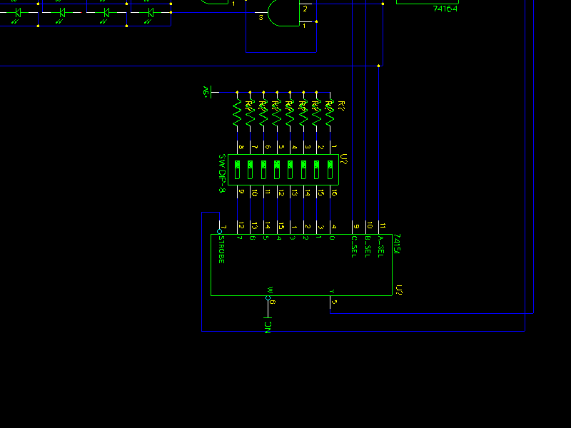
For the input, due to I/O constraints on the MSP430 (10 pins), I'm thinking we'll use an 8:1 multiplexer which we'll layout kind of like this:
Notice we use the LSBs of the Column Select shift register to control the select lines of our 8:1 multiplexer, so we can address our 8 switches and to prevent the noise of shifting our select bits in, we'll just turn the OE off and voila no display for a fraction of a second while we poll for data when needed.
Now the MSP430 ties together with these other components to make a near complete schematic.
When the pushbutton on P1.2 (at top, 1 resistor + pushbutton) is pressed, we'll read in the values through the mux, then we'll a display the corresponding ascii character. So in the next post we'll talk about the shortcomings (if I missed something) and the software to drive this groovy display. I may also look into how to get the chip to turn off the display peripherals when it's been inactive for a couple minutes, and other similar things.
Now, my boss asked if I could develop a device to assist in a lesson concerning binary and computation. I thought for a moment and realized that "Why yes, yes I can." I've always been a fan of near instant feed back. It's mostly why I work with computers. So here's the design needs for now:
1. 8 Bit data entry
2. Display corresponding ASCII character
3. Data entry needs to be easy enough for a child to use.
4. We're not all rich so it needs to be fairly cheap.
So here's the plan:
8 switches of some sort + 1 push button for "Enter" (Multiplexed)
8x8 LED Matrix Display
MSP430Gx2xx (TI Launchpad, for grins)
For the display, we'll use the matrix and we'll drive it with 2 8 bit shift registers (more info) and some AND gates for output enabling. The basic layout in my head looks like this:
 |
| Display Driver |
Notice we feed the Row Select shift register CLK (outer wire at bottom) with the rising edge of the LSB of the Column Select shift register. This will allow us to do entries into the row select only when we're toggling the LSB of the column, this will present some interesting coding challenges.
Originally I didn't have the transistors in there, and then I kinda remembered that the row shift register won't be able to sink the sourced current of the column shift register due to being in high impedance. So we use npn transistors (3904 because I had a bag of them laying around) to sink the current, controlled by the row select shift register, and series in some 500 ohm resistors on the a collector side to protect our LED matrix (which by the way is the most expensive part of this project!)
For the input, due to I/O constraints on the MSP430 (10 pins), I'm thinking we'll use an 8:1 multiplexer which we'll layout kind of like this:
 |
| Data Input (8:1 Mutiplexer) |
Notice we use the LSBs of the Column Select shift register to control the select lines of our 8:1 multiplexer, so we can address our 8 switches and to prevent the noise of shifting our select bits in, we'll just turn the OE off and voila no display for a fraction of a second while we poll for data when needed.
Now the MSP430 ties together with these other components to make a near complete schematic.
 |
| Whole circuit |
When the pushbutton on P1.2 (at top, 1 resistor + pushbutton) is pressed, we'll read in the values through the mux, then we'll a display the corresponding ascii character. So in the next post we'll talk about the shortcomings (if I missed something) and the software to drive this groovy display. I may also look into how to get the chip to turn off the display peripherals when it's been inactive for a couple minutes, and other similar things.
Thursday, October 21, 2010
Accessing a MS SQL database in R
I'm going to preface this post with a disclaimer: I'm not really a programmer - I'm actually an ecologist. That being said, I am slowly learning R in the course of my work. R is a programming language and a software environment for doing statistics and making pictures with data. A lot of programmers have never heard of R and those who come to R after learning other languages may complain bitterly about it. Since R is the first language I've learned, I can't really tell you how it's different from other languages, but I can tell you that I struggled quite a bit with the syntax because there are many ways to seemingly do the same thing. But the very subtle differences will kill your code.
With all this talk of death, you're probably as frightened of R as the average ecologist, but there are very good reasons to use R (even the NY Times thinks so!). If you're doing data analysis, you can do it with R and you can probably do it better. Plus, it's free.
To get you familiar with R and some of its capabilities, I'm going to walk you through one of my current projects over a few posts. My lab group has data from several remote weather stations stored in a Microsoft SQL Database. Temperature and precipitation have been measured hourly for about eight years. For a variety of reasons, we have quite a few missing measurements. I need to create a model that (reasonably) predicts those missing values.
The first step is to actually get to the data. Those of you familiar with databases probably wouldn't have had to spend an entire afternoon trying to do that. Those of you not familiar with databases hopefully won't spend all afternoon trying to do that after reading this post. A quick note: I use Windows at work. If you're using something else, this may not be as helpful as I'd hope.
Create Data Source Name
We're going to use ODBC to get R to communicate with the database. Before today, I didn't have a good handle on ODBC. Wikipedia was totally there for me:
Open Database Connectivity (ODBC) provides a standard software interface for accessing database management systems (DBMS). The designers of ODBC aimed to make it independent of programming languages, database systems, and operating systems. Thus, any application can use ODBC to query data from a database, regardless of the platform it is on or DBMS it uses. ODBC accomplishes this by using a driver as a translation layer between the application and the DBMS. The application thus only needs to know ODBC syntax, and the driver can then pass the query to the DBMS in its native format, returning the data in a format the application can understand.
Cool, right? So to get this all working, the first thing you need to do is create a Database Source Name for your database. I didn't really know what that was either, but of course Wikipedia did:
A DSN specifies a data structure that contains the information about a specific data source (database or other data source) that an Open Database Connectivity (ODBC) driver needs in order to connect to it.
Luckily, this is really easy to do and Microsoft will hold your hand the whole way:
Create a System DSN in Windows XP
- Click Start, point to Control Panel, double-click Administrative Tools, and then double-click Data Sources(ODBC).
- Click the System DSN tab, and then click Add.
- Click the database driver that corresponds with the database type to which you are connecting, and then click Finish.
- Type the data source name. Make sure that you choose a name that you can remember. You will need to use this name later.
- Click Select.
- Click the correct database, and then click OK.
- Click OK, and then click OK.
Install RODBC package
The next step is even easier. Assuming you already have R installed, you need to install and load the RODBC package. There are a lot of ways to install packages in R, but I installed and loaded the package like so:
install.packages('RODBC') #installAnything after a # is a comment in R.
library('RODBC') #load
Connect to the database
And we're ready to connect! All I need to do now is give the odbcConnect function the name of the DSN I created and my username and password. I'll call this connection con. You can call it anything you like, as long as it doesn't have spaces or start with a number.
con <- odbcConnect('DSN', uid='username', pwd='password')
The quotes are important. If you don't use them, R thinks you're referring to an object.
Now that I have access to the database through con, I want to know a little bit about the database. odbcGetInfo(con) will tell you some basic information about the database like what database management system you're using, what version you're using, and the name. That's not especially helpful since you should already know these things.
The sqlTables function will return all table like objects. I just want to see what the actual tables are, so I pass it an additional argument, like so:
If I want to know the column names and data types in a particular table I can use the function sqlColumns.
You can learn more about what you can do with the RODBC package in this handy document (pdf). In my next post I'll query the database through the connection I've created and do some basic data manipulation in preparation for running a model.
Now that I have access to the database through con, I want to know a little bit about the database. odbcGetInfo(con) will tell you some basic information about the database like what database management system you're using, what version you're using, and the name. That's not especially helpful since you should already know these things.
The sqlTables function will return all table like objects. I just want to see what the actual tables are, so I pass it an additional argument, like so:
sqlTables(con, tableType='TABLE')The parameter tableType is case sensitive, but the argument TABLE isn't. That won't always be the case with an R function. Figuring out errors caused by using the wrong case is a great time.
If I want to know the column names and data types in a particular table I can use the function sqlColumns.
sqlColumns(con, sqtable='hrlyweather')I could have returned the same output with
sqlColumns(con, 'hrlyweather')R functions will usually let you get away with leaving off the parameter name (sqtable in this case) as long as you pass the function arguments in the order it expects, but it's a good habit to use the parameter names. It'll make it easier to figure out problems and make your code much more readable.
You can learn more about what you can do with the RODBC package in this handy document (pdf). In my next post I'll query the database through the connection I've created and do some basic data manipulation in preparation for running a model.
Subscribe to:
Posts (Atom)